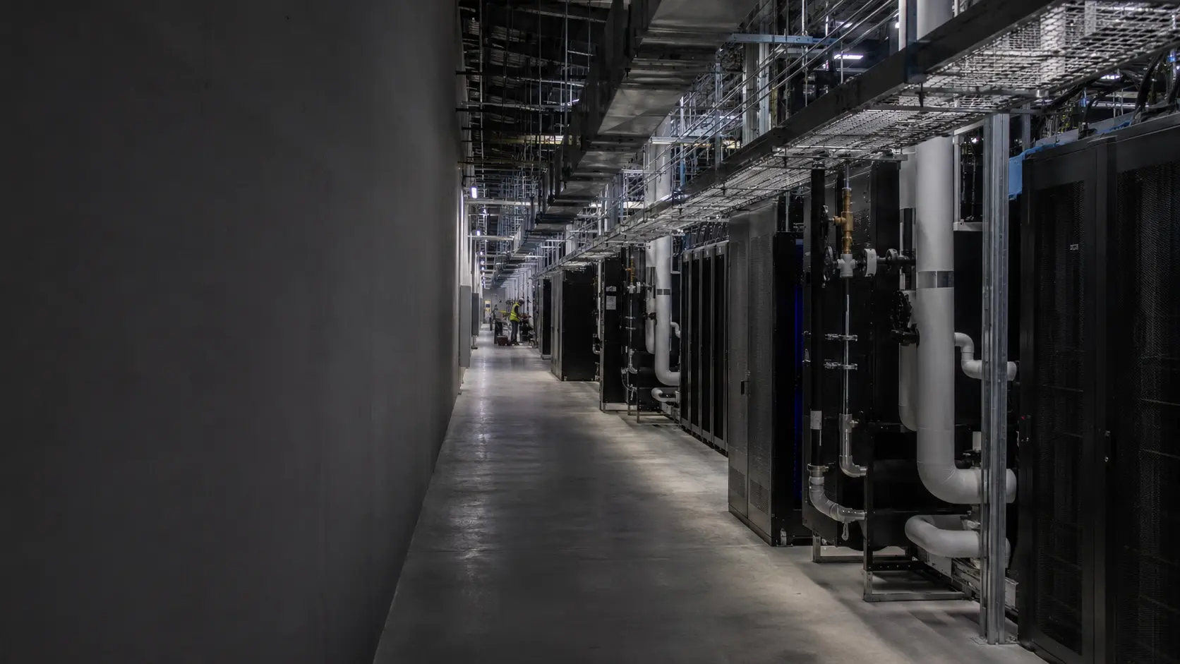
Site & Power
Define the feasible power envelope across utility availability, interconnect timing, substation topology, redundancy, and campus load.
Output
Power envelope + site criteria
4AI Factory brings site, power, liquid cooling, compute, fabric, storage, commissioning, and operating readiness into one deployment plan—before long-lead procurement begins.
One coordinated deployment plan
01 / Capabilities
We turn capacity and workload requirements into a buildable basis of design, delivery sequence, acceptance criteria, and operating model.
Define the feasible power envelope across utility availability, interconnect timing, substation topology, redundancy, and campus load.
Power envelope + site criteria
Translate workload and scale into rack, fabric, storage, management, and software-control requirements.
Basis of design + topology
Engineer facility water, heat rejection, CDUs, distribution, controls, and service access as one coordinated loop.
Thermal basis + controls
Set integration gates, acceptance tests, observability, spares, and handoff requirements before installation starts.
Acceptance plan + runbooks
Method, not theater
Infrastructure credibility comes from what gets resolved, recorded, and accepted—not from a parts list or a concept image.
Decision-ready deliverables
Deployment brief and assumptions ledger
Integrated basis of design
Long-lead dependency plan
Commissioning and acceptance plan
Operating model and expansion triggers
02 / System
This scenario shows how compute, fabric, storage, controls, thermal, and facility systems fit together. Final topology, resilience, load, and component choices depend on the site, workload, and supplier availability.
Facility + thermal + rack + control layers
Illustrative only. Not a customer deployment, validated reference design, availability commitment, or operating capacity.
One production envelope from the utility edge to the operating model.
Capacity, topology, resilience, and the interconnect critical path.
Heat rejection, facility water, CDUs, distribution, and controls.
Electrical and liquid boundaries designed around density and service.
A workload-led topology rather than a vendor-led parts list.
Telemetry, acceptance criteria, runbooks, and expansion triggers.
03 / Risk control
The expensive failures happen at system boundaries. We make those boundaries explicit before they become field problems.
What can the site support—and when?
Resolve feasible load, interconnect timing, redundancy, and mechanical overhead before the hardware plan hardens.
Can every watt leave the system?
Model facility water, heat rejection, flow, pressure, chemistry, controls, and service conditions as one loop.
What actually sets the schedule?
Map long-lead equipment, design decisions, integration gates, substitutions, and site readiness against one critical path.
What does ready mean?
Define test evidence, telemetry, failover behavior, runbooks, spares, and handoff criteria before commissioning begins.
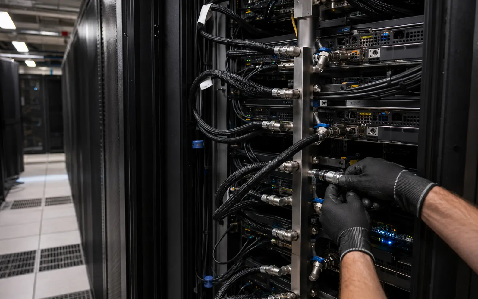 Illustrative maintenance view
04 / Thermal
Direct-to-chip liquid cooling is not an accessory. The complete loop—from facility water and heat rejection through CDUs, manifolds, rack connections, controls, and serviceability—must be engineered together.
Temperature, flow, pressure, and chemistry modeled together
Resilience aligned to workload and maintenance windows
Acceptance evidence from heat rejection to cold plate
05 / Energy
Utility capacity, interconnect timing, substation topology, and mechanical load determine feasible cluster size and schedule. Resolve that envelope before procurement decisions lock in risk.
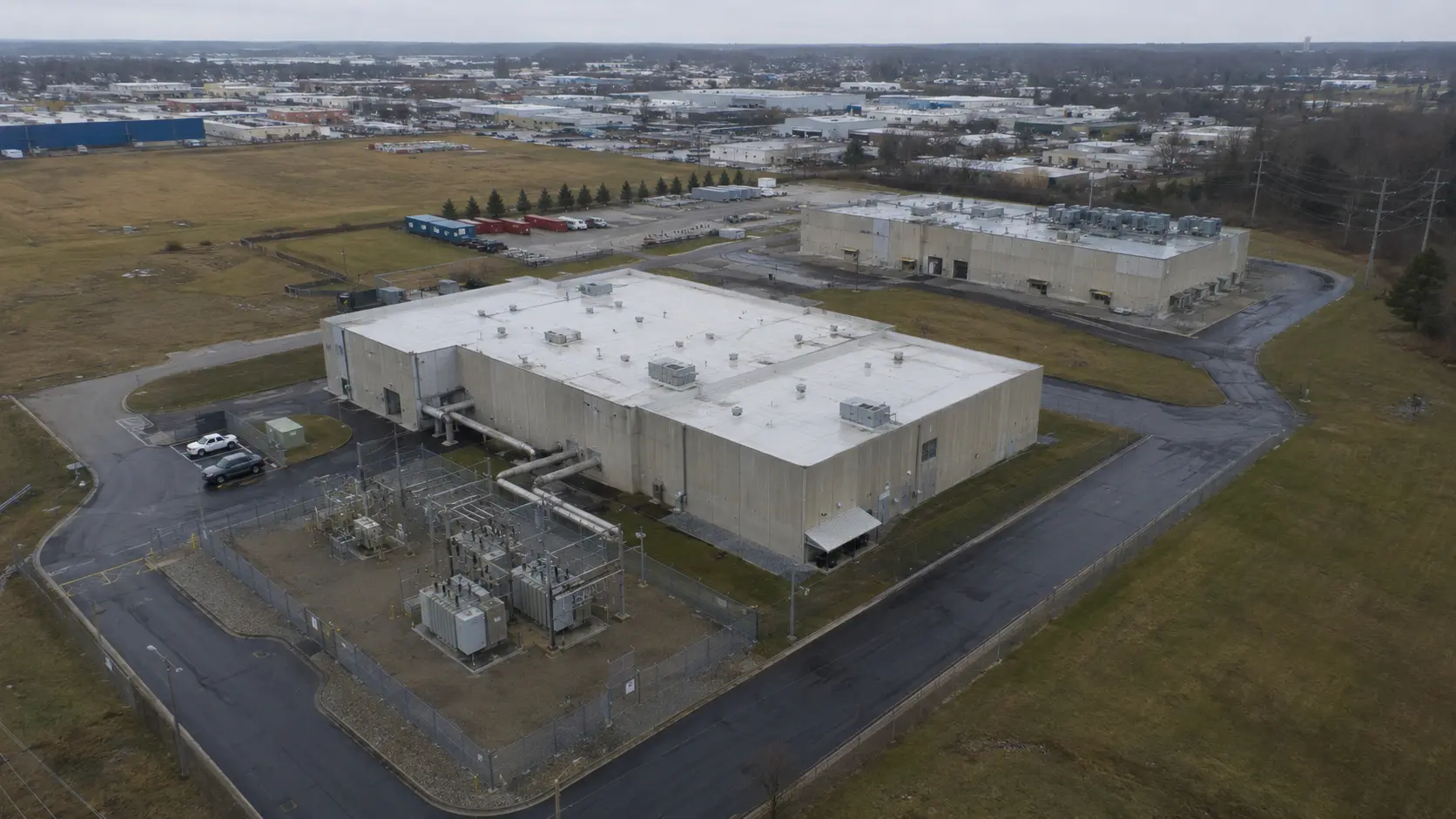 Illustrative campus view
One capacity envelope, validated per site.
06 / Delivery
Confirm workload, capacity, site, resilience, economics, and schedule. Record the assumptions driving the design.
Produce the basis of design across power, thermal, rack, fabric, storage, controls, and operating model.
Coordinate long-lead items, integration, installation, and test sequencing against defined decision gates.
Commission against agreed criteria and hand off runbooks, observability, and expansion triggers.
Deployment brief
Choose scale, system approach, site readiness, and target window. We will assemble a concise scope you can copy, share, and refine.
A planning artifact—not a quote, schedule commitment, or validated design.